


6061 Aluminum Machining: Simplify Design to Cut Costs
Published on Thursday, 19. March 2026
Content Guide:Optimize 6061 aluminum part costs & accelerate time-to-market with expert DFM. This guide for R&D engineers reveals how early supplier collaboration analyzes design for manufacturability, optimizing structure, tolerances & features to cut material, labor & yield costs while ensuring performance. Lea
In the fiercely competitive field of product development, controlling costs and accelerating time-to-market are perpetual challenges. For 6061 aluminum alloy parts widely used in aerospace, consumer electronics, automation equipment, and other sectors, their final cost is largely determined early on in the CAD drawings of R&D engineers. The traditional linear process of "design-release-manufacture" often leads to designs encountering machining difficulties, soaring costs, and delivery delays due to insufficient consideration of manufacturing constraints. This article aims to provide R&D engineers and project decision-makers with an in-depth analysis of how professional machining suppliers, during the initial product design phase, can optimize the structure, tolerances, and features of 6061 aluminum parts at the source through systematic Design for Manufacturability (DFM) analysis. This approach achieves a comprehensive reduction in material, labor, and yield-related costs while ensuring performance.
I. DFM: Bridging Design and Manufacturing
Design for Manufacturability is not simply about making a design "easy to machine." It is a systematic engineering methodology that, under the premise of guaranteeing product function, quality, and reliability, optimizes the design to simplify manufacturing processes, reduce production costs, and improve production efficiency. For the milling of 6061 aluminum, the core of DFM lies in a deep understanding of material properties (such as good machinability and moderate strength), machine tool capabilities (such as dynamic accuracy, tool interference), and machining economics (such as setup times, tool wear). The early involvement of professional suppliers precisely injects this manufacturing-side "knowledge asset" into the design phase, avoiding costly design rework.

Schematic comparison of a part before and after DFM optimization
II. Key DFM Strategies and Case Studies for Milling 6061 Aluminum Parts
The following combines specific cases to explain core DFM recommendations for milling processes under general precision requirements (±0.05mm).
1. Structural Optimization: Reducing Material and Machining Volume
Strategy: In non-critical load-bearing areas, replace solid, bulky structures with hollowed-out sections, weight-reduction pockets, and reinforcing ribs. This not only saves expensive raw materials but also significantly reduces milling time and tool wear.
Case Study: An aluminum plate used for an equipment bracket was initially designed as a 50mm thick solid plate, requiring only a few mounting holes to be machined. DFM analysis revealed its core function was to provide mounting surfaces and connection strength. After optimization, while ensuring the thickness of mounting surfaces and the strength of key connection points, the interior was hollowed out into a rib-reinforced cavity structure. The overall weight was reduced by over 40%, with material costs and rough machining time decreasing proportionally.
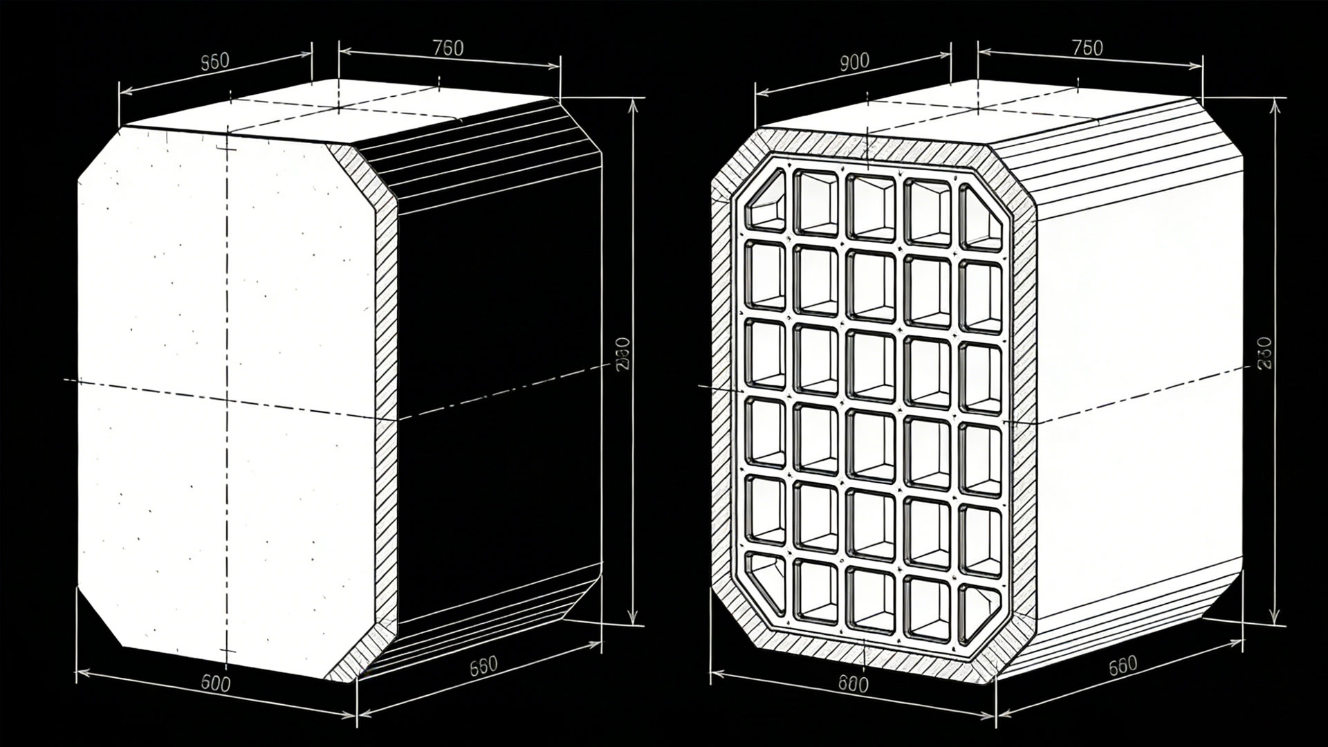
Achieving lightweighting through internal hollowing and rib design
2. Feature Simplification: Avoiding Unnecessary Machining Challenges
Strategy: Simplify or modify features that require special tools, non-standard processes, or extremely high machine tool precision.
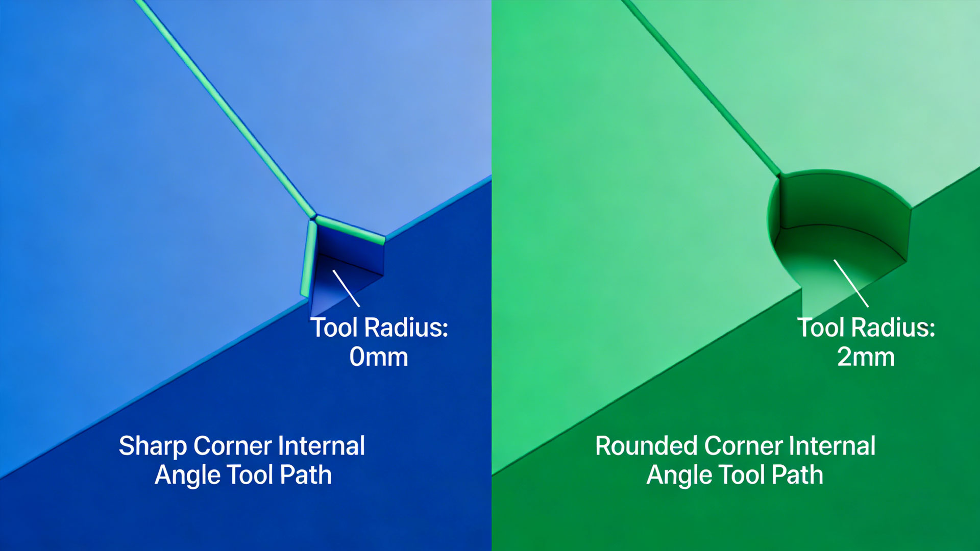
Case A (Internal Corners): Internal vertical corners in a design, if requiring sharp corners, necessitate the use of very small diameter tools, resulting in low machining efficiency and high tool breakage risk. DFM recommends adding a radius (e.g., R3 or larger) to all internal corners, matching common end mill diameters. This allows the use of larger diameter tools and higher feed rates for contour machining, potentially improving efficiency several times over.
Case B (Deep Pockets/Narrow Slots): Designing a narrow slot with a depth exceeding 50mm and a width of only 4mm requires custom, non-standard tools with an extremely high length-to-diameter ratio. This leads to severe chatter, difficulty maintaining precision, and very high cost. DFM suggests consulting with the engineer to see if, functionally permissible, the slot width can be increased to 6mm or more (matching standard tool diameters) or changed to a segmented shallow slot design. This immediately allows the use of standard tools, significantly improving machining stability and cost-effectiveness.
3. Tolerance Rationalization: Balancing Performance and Manufacturing Cost
Strategy: Rigorously assess the necessity of each dimensional tolerance. Relax tolerances for non-critical fit dimensions to an economical precision range (e.g., ±0.1mm or wider), reserving tight tolerances (±0.05mm or stricter) only for key functional surfaces. Tightening a tolerance by one grade often necessitates adding finishing operations, reducing feed rates, or requiring secondary setups, leading to an exponential increase in cost.
Case Study: For an aluminum housing, all external dimensions were initially specified as ±0.05mm. DFM analysis revealed that only the sealing groove and main mounting interfaces required this precision for proper assembly. Tolerances for the remaining non-mating aesthetic surfaces could be relaxed to ±0.15mm. This adjustment allowed most of the profile to be completed using more efficient roughing and semi-finishing milling strategies, saving approximately 25% in machining time.
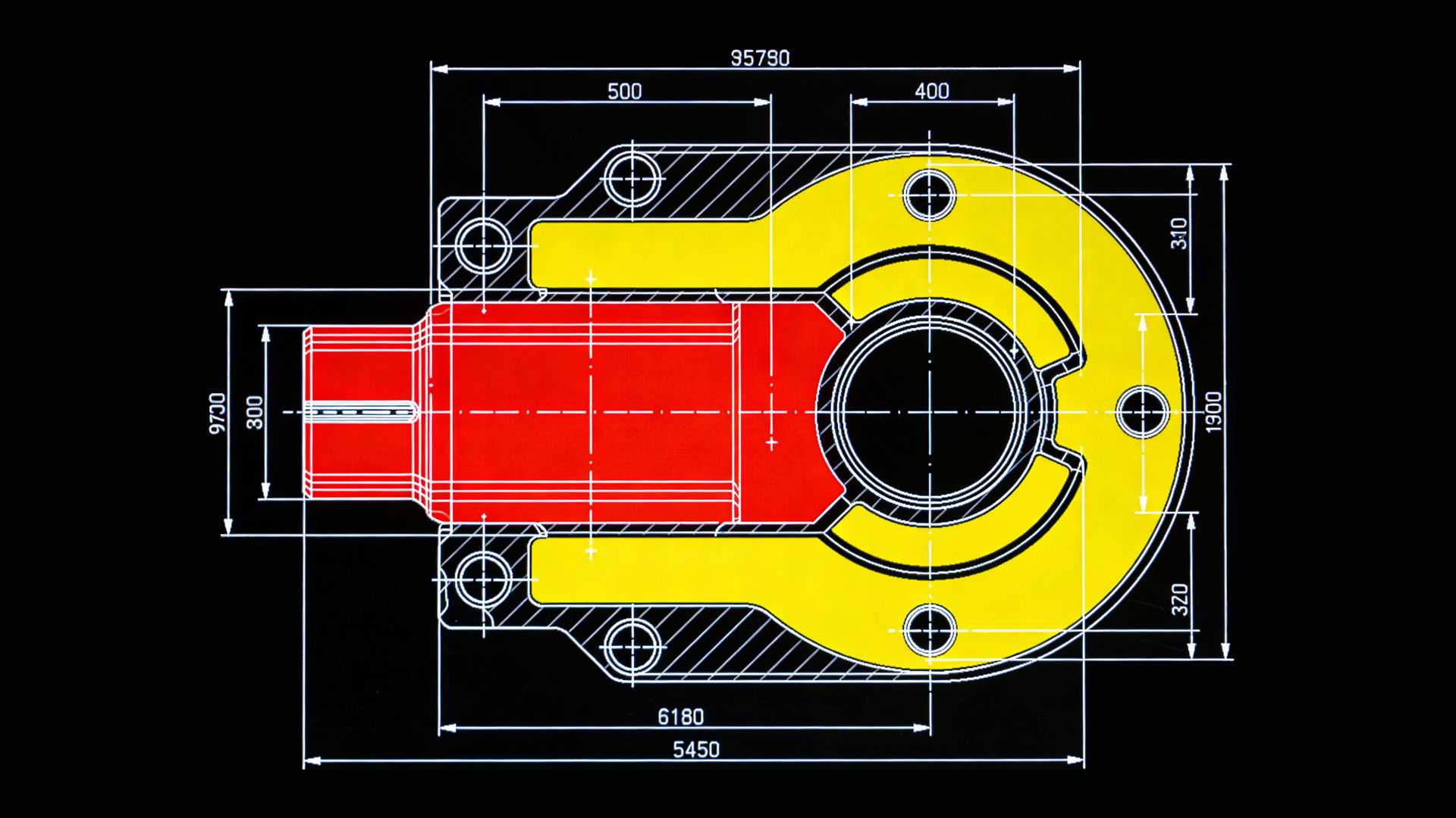
Identification and differentiation of key and non-key tolerance zones
4. Fixturing and Datum Design: Laying the Foundation for Efficient Production
Strategy: Consider the part's fixturing method on the machine tool table during the design phase. Provide ample, flat clamping surfaces and arrange multiple features in the same setup orientation where possible to minimize part flips. Clearly define design datums and align them with machining datums.
Case Study: A part requiring machining on five faces originally lacked clear clamping bosses or sacrificial tabs, necessitating complex custom fixtures or multiple setups. DFM recommendations included adding several small, non-functional process bosses in non-critical areas to serve as clamping surfaces, enabling all critical features to be machined within two setups. These bosses were easily removed post-machining. This change reduced the number of setups from five to two, significantly improving consistency and efficiency.
III. Summary and Outlook
The analysis above demonstrates that optimizing the total cost of milling 6061 aluminum parts is a systematic engineering effort that begins at the design stage. The DFM service provided by professional machining suppliers essentially translates manufacturing experience, constraints, and economic considerations into specific, actionable design optimization recommendations. Its core value is reflected in: reducing material consumption, decreasing machining time and tooling costs, improving first-pass yield, and shortening the overall delivery cycle.
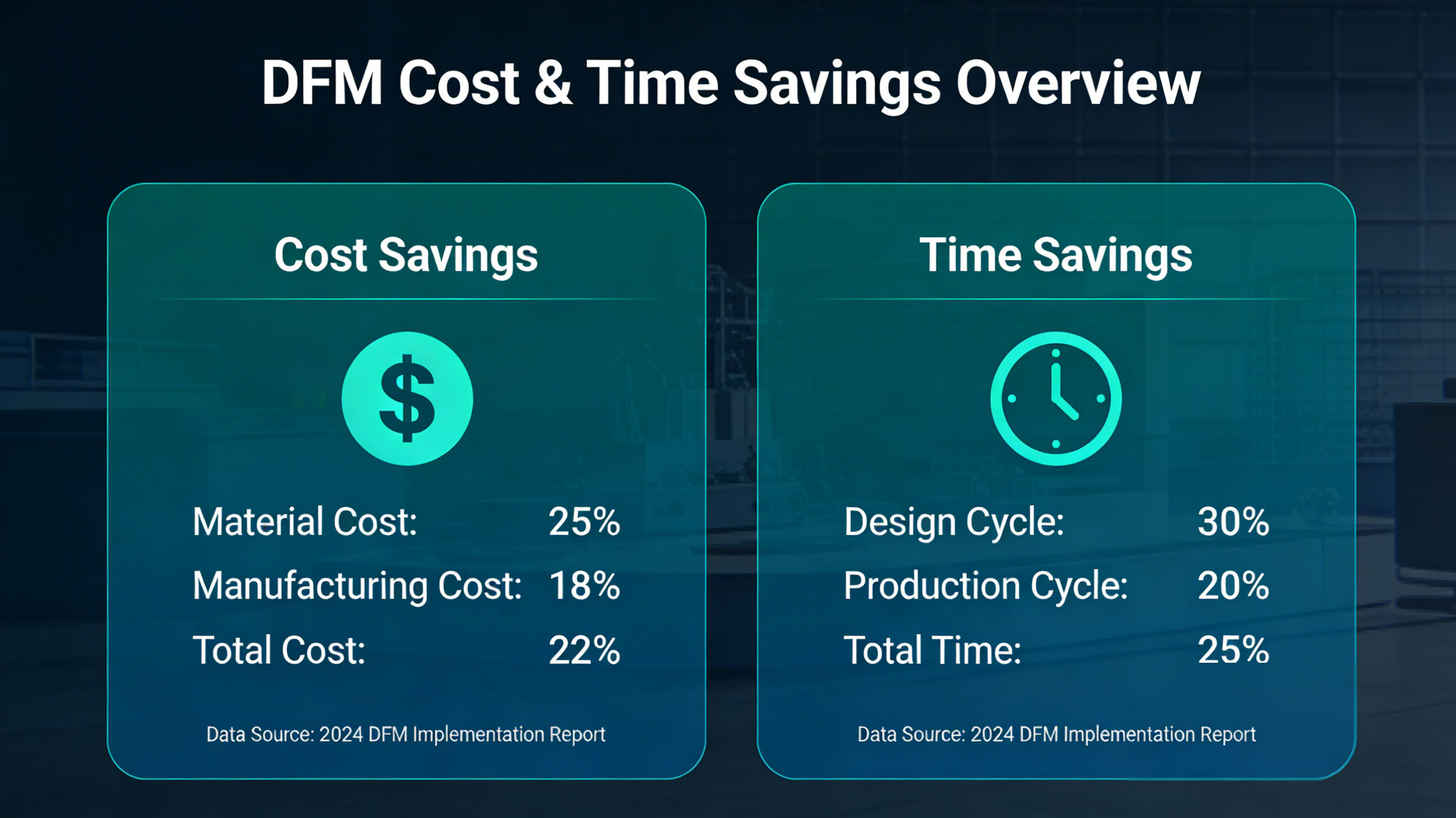
Impact trend chart of early DFM involvement on total project cost and timeline
We recommend that the R&D team regard the manufacturing experts from suppliers as "collaborative design partners" and involve them from the product concept finalization and detailed design stages. A brief DFM meeting or drawing review can prevent potential costs and risks far exceeding the investment. Looking ahead, with the development of digitalization and intelligence, cloud-shared DFM inspection software and knowledge bases will make this collaboration more seamless and efficient. However, regardless of how it evolves, the core concept remains unchanged: the best cost control occurs before the first drawing is created.


Ready to transform your CAD file into a custom part? Upload your design to get a free, precise quote.
Get Your Instant Quote