


PEEK Machined Parts Quality Inspection Guide: Standards & Methods
Published on Wednesday, 25. March 2026
Content Guide:Master PEEK parts inspection with this essential guide for rough machining (±0.1mm). Learn critical temperature compensation for dimensional accuracy, key visual defect criteria for melt marks & burrs, and special validation for chemical/electrical performance.
This specification aims to provide clear guidance for the quality inspection of precision-machined parts made from PEEK (Polyetheretherketone) material. As a high-performance specialty engineering plastic, PEEK's physical properties (such as high coefficient of thermal expansion and relatively soft texture) differ significantly from those of metals, necessitating specially tailored inspection standards. This document focuses on the rough machining stage (tolerance ±0.1mm), targets frontline operators, and defines key inspection requirements from dimensions and appearance to special properties, ensuring the parts meet subsequent application needs.
1. Dimensional Measurement Specification and Temperature Compensation
The coefficient of thermal expansion for PEEK material (approximately 4.7×10⁻⁵ /°C) is much higher than that of metals (e.g., steel approximately 1.2×10⁻⁵ /°C). Fluctuations in ambient temperature significantly affect measurement results, making temperature compensation essential.
1.1 Measurement Environment Requirements
Measurements should be conducted in a constant temperature room, with an ideal temperature of 20±2°C. Parts must be allowed to rest in this environment for at least 4 hours before measurement to fully equilibrate their temperature with the measurement environment.
1.2 Temperature Compensation Method
If the measurement environment temperature (T) deviates from the standard 20°C, the measured dimension (L_measured) must be compensated. The formula for calculating the compensated dimension (L_standard) is: L_standard = L_measured × [1 - 4.7×10⁻⁵ × (T - 20)]. For example, a part measured to be 100.00 mm long at 25°C would have a standard length at 20°C of approximately 99.98 mm. Operators should use measuring tools equipped with temperature sensors and automatic compensation functions, or apply manual correction based on the above formula.
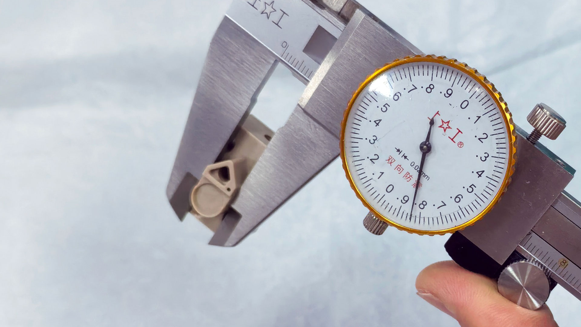
Dimensional measurement of a PEEK part in a constant temperature environment
II. Acceptance Criteria for Appearance Defect Classification
PEEK is prone to characteristic appearance defects during milling. The judgment criteria are as follows:
1. Melt Marks and Whitening
Caused by localized melting or crystallinity changes due to excessive machining heat. Acceptance Criterion: Slight, scattered whitening spots or minute melt marks (diameter ≤ 0.5mm) are allowed, with no more than 3 occurrences per 100mm². Continuous or large-area melting or charring marks are not permitted.
2. Fiber Exposure (For Carbon/Glass Fiber Reinforced PEEK)
Machining causes reinforcing fibers to become exposed. Acceptance Criterion: Individual exposed fiber endpoints (length ≤ 0.3mm) are allowed, but clumps, patches, peeling, or lifting of fibers are not permitted.
3. Burrs
Acceptance Criterion: Slight burrs that are not sharp to the touch (height ≤ 0.05mm) are allowed on all sharp edges. Burrs on critical assembly or sealing surfaces must be completely removed.
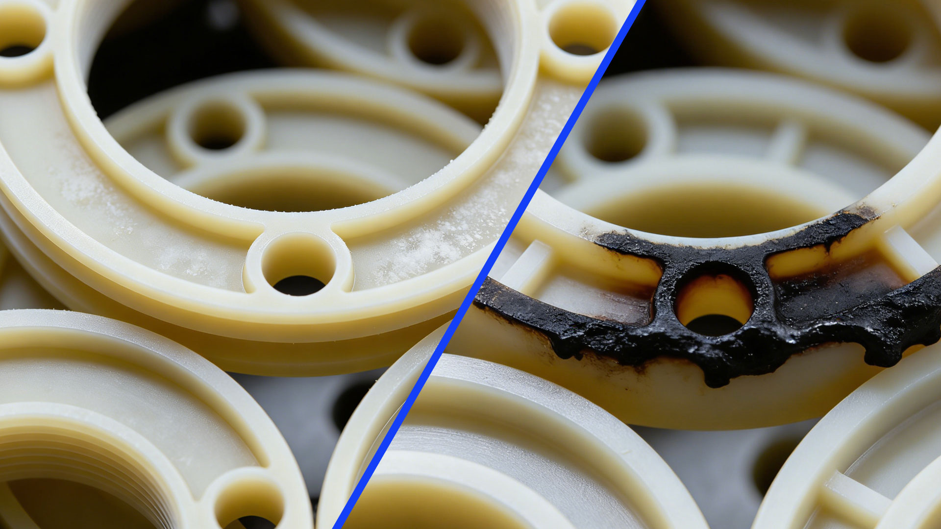
PEEK Appearance Defect (Melting and Whitening) Judgment Examples
III. Special Performance Validation for Critical Applications
Depending on the part's end use, the following validation items may be required:
1. Chemical Resistance Validation
If the part will contact specific chemicals (e.g., engine oil, acid/alkali solvents), immersion testing is required. Method: Process test pieces from the same material batch, immerse them in the specified chemical medium at the specified temperature for the specified duration, then inspect for weight change rate, dimensional change, and surface cracking or dissolution. The change rates must meet drawing or technical agreement requirements.
2. Insulation Performance Test
For parts used in electrical insulation, insulation resistance or withstand voltage testing is required. Using an insulation resistance tester, measure the resistance value under specified electrode distance and voltage (e.g., 500VDC). Typically, insulation resistance ≥ 1×10¹² Ω is required. Withstand voltage testing applies high voltage according to safety standards to check for breakdown.
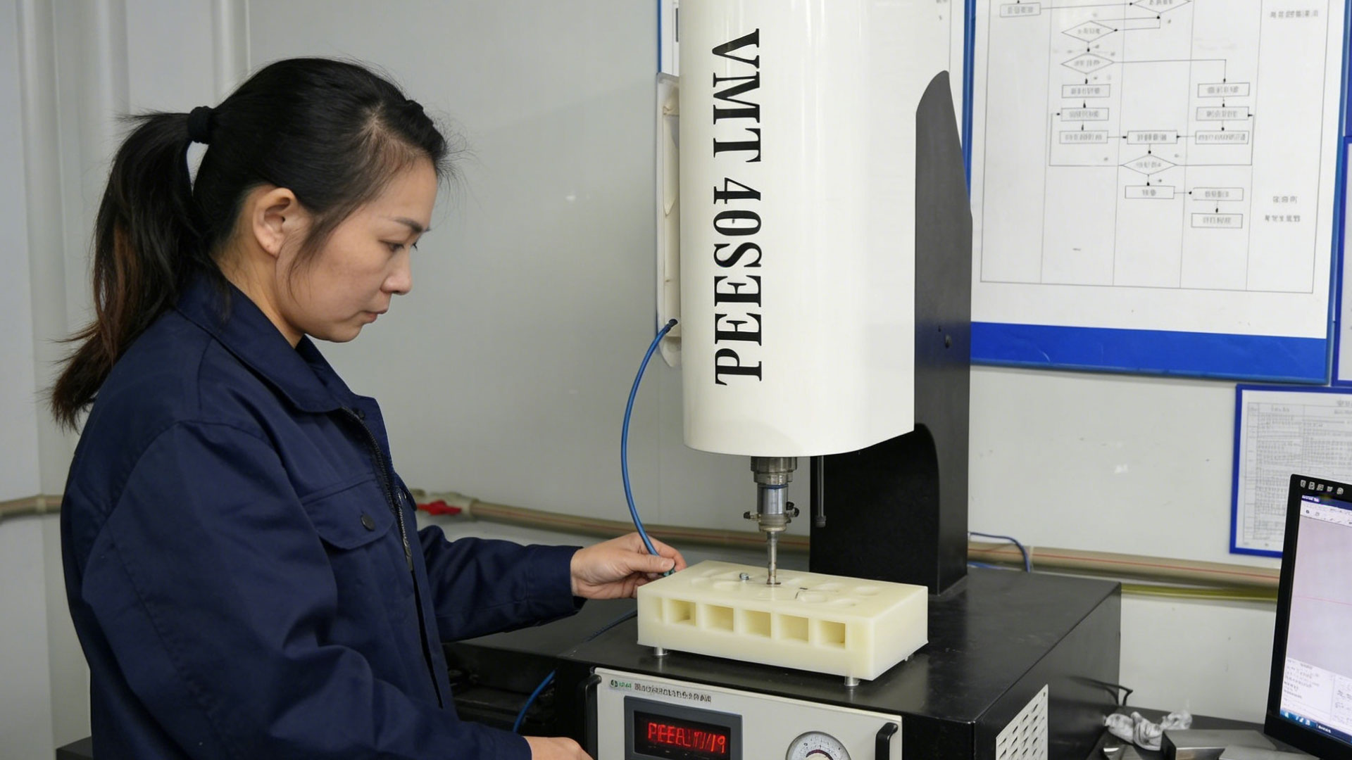
PEEK Part Insulation Performance Validation Test
IV. Summary and Key Points
The core of inspecting PEEK components lies in "tailoring inspection to the material": dimensional measurements must account for ambient temperature and apply compensation; visual defect inspection should focus on overheating and fiber handling issues; validation of special properties must be closely tied to actual application scenarios. During inspection, operators should strictly adhere to this specification and specific drawing requirements, documenting and reporting any anomalies. Standardized inspection effectively ensures the reliability of precision-machined PEEK parts, meeting the application demands in high-end fields such as semiconductors, medical devices, and aerospace.
Ready to transform your CAD file into a custom part? Upload your design to get a free, precise quote.
Get Your Instant Quote


